
Help · Installation
VEM LED Display — Installation Guide
Every VEM screen is built from the same 2′ × 1′ panel, repeated across and high. Enter your screen size from sheet 1 of your project layout — this guide redraws itself for your screen.
Your screen
- Model
- VEM 9 · 9.525 mm
- Panels
- 5 × 5 = 25
- Screen size
- 10′ W × 5′ H
- In mm
- 3,048 × 1,524
- Resolution
- 320 × 160 px
- Frame bolts
- 80 × M8 × 50
- Power feeds
- 5 (one per row)
- Max power
- 3,325 W · 27.7 A
- Weight
- ≈ 358 lb (162 kg)
Your project layout sheets are the final word. If a number here and your sheet differ, follow the sheet.
1 — Know your parts
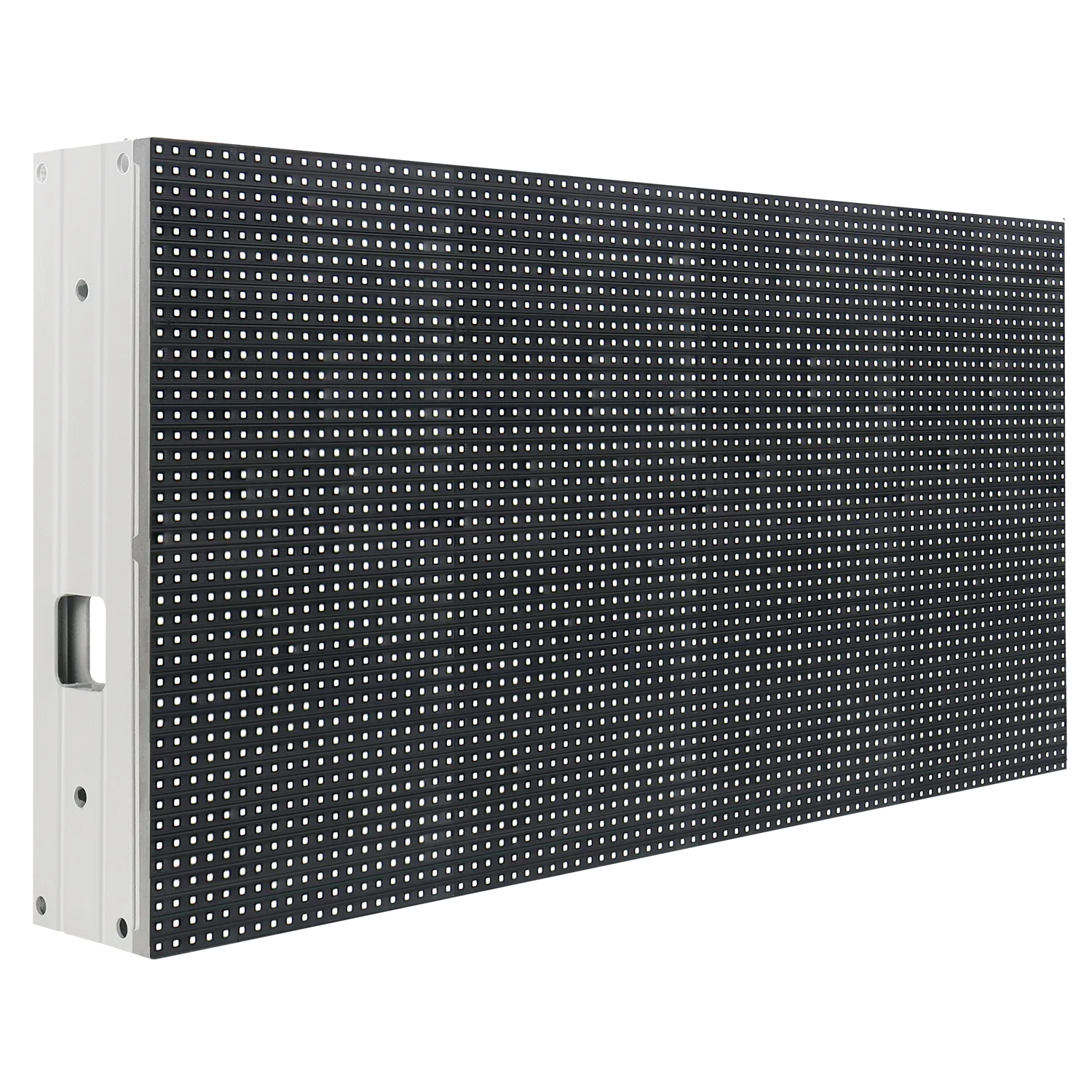
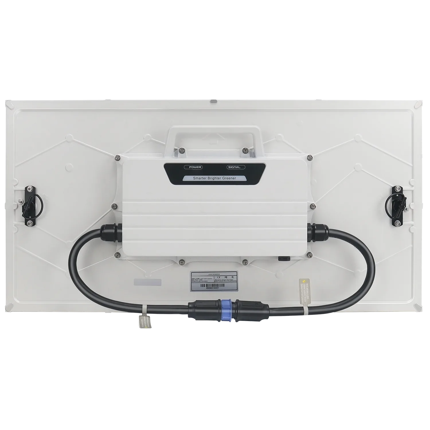
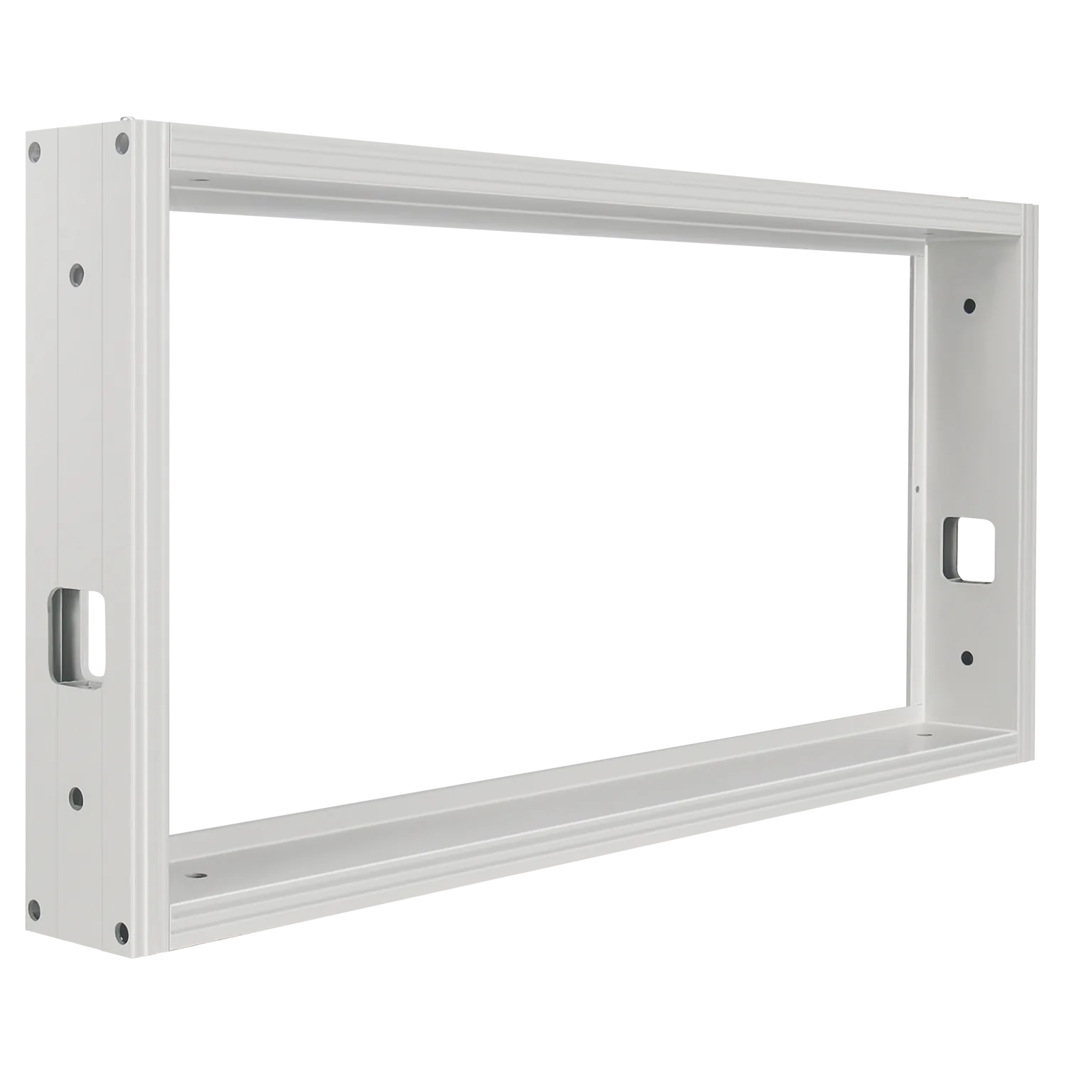
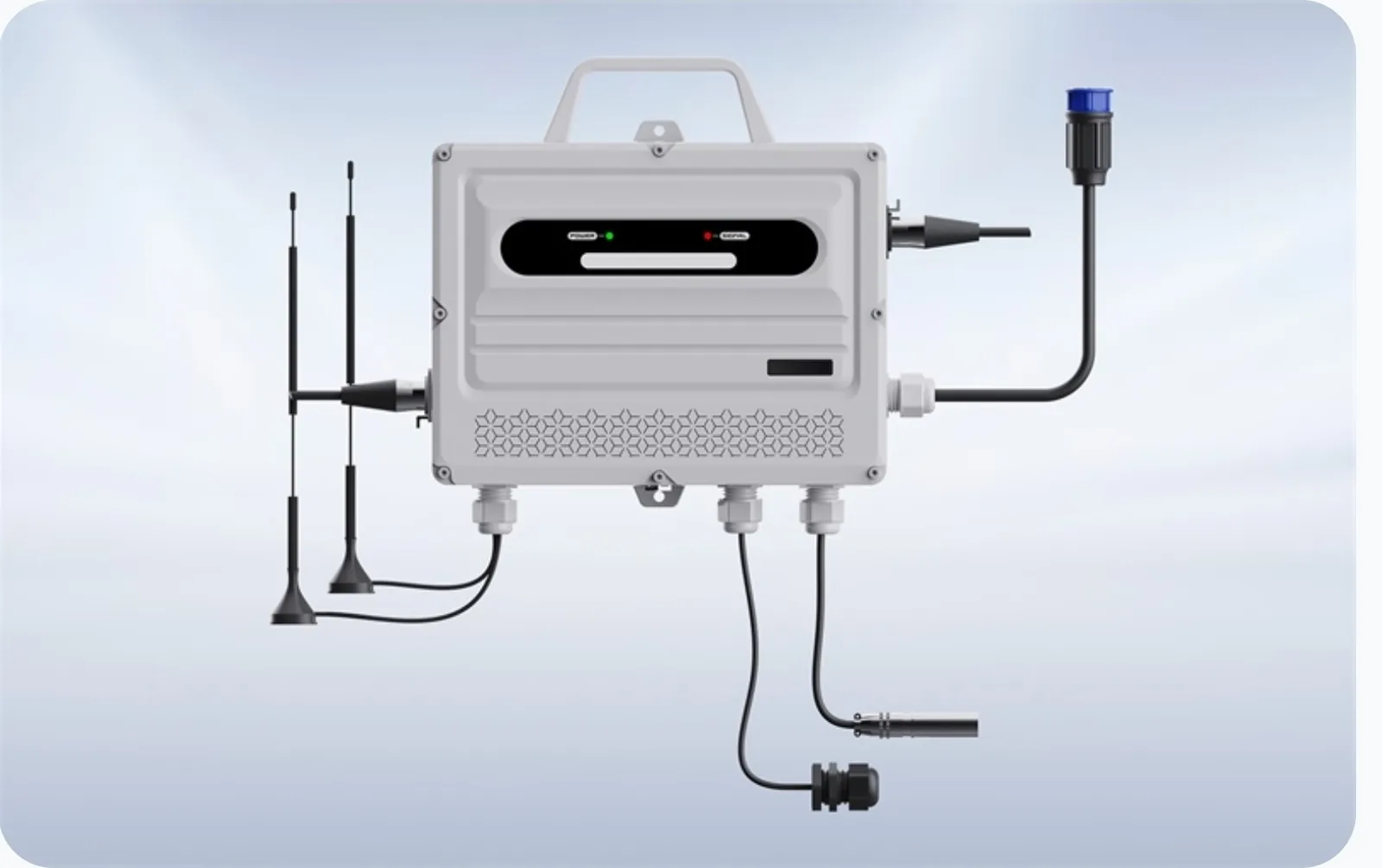
Every panel is the same — any panel can go in any spot. The controller tells each panel what to show.
What's in the box for your screen
Quantities update when you change your screen size above.
| Picture | Part | Qty | Used for |
|---|---|---|---|
| VEM 9 panel in aluminum frameThe screen — any panel fits any spot | 25 | The screen — any panel fits any spot |
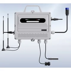 | ControllerSends the picture to the screen (primary + backup data) | 1 | Sends the picture to the screen (primary + backup data) |
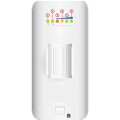 | Wireless bridgeOne at the sign, one at your building | 1 pair | One at the sign, one at your building |
 | Aviation plug network cableController to the wireless bridge (LAN) | 1 | Controller to the wireless bridge (LAN) |
 | 9+0 aviation plug signal cableController to the screen | 1 | Controller to the screen |
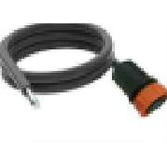 | 0+3 wire power cableOne per row — brings power in | 5 | One per row — brings power in |
 | Four-male adapterLeft side: brings power in and loops data between two rows | 3 | Left side: brings power in and loops data between two rows |
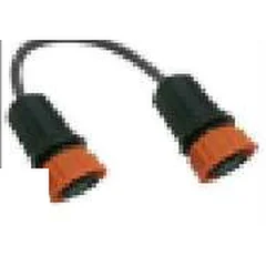 | 9+0 double-female signal cableRight side: loops data from one row to the next | 2 | Right side: loops data from one row to the next |
 | Screws and nuts M8 × 50Frame to frame (4 per frame, minus 1 per outside edge) | 80 | Frame to frame (4 per frame, minus 1 per outside edge) |
 | Sealing capCovers the last open data port | 1 | Covers the last open data port |
| Small T-handle Allen key (thin)Locks and unlocks the panels — front service | 1 | Locks and unlocks the panels — front service | |
| Large T-handle Allen key (thick)Tightens the M8 bolts | 1 | Tightens the M8 bolts |
2 — Unpack
Step 1: Open every box and lay everything out
Use a clean table or tarp. Count panels and kit parts against sheet 3 of your layout.
Missing or damaged? Submit a support ticket before you start.
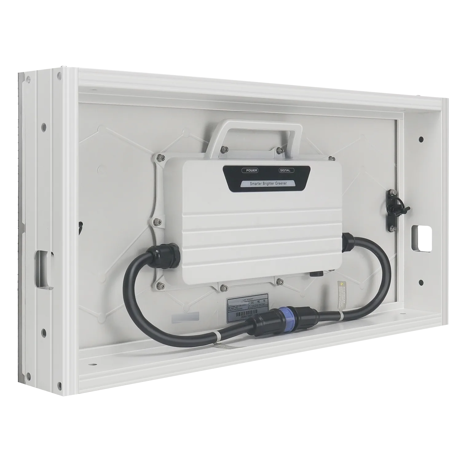
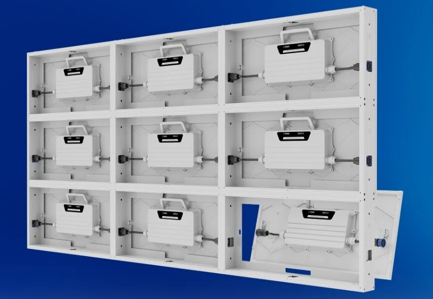
Step 2: Take each panel out of its frame — from the back
Turn the frame face down on a soft surface.
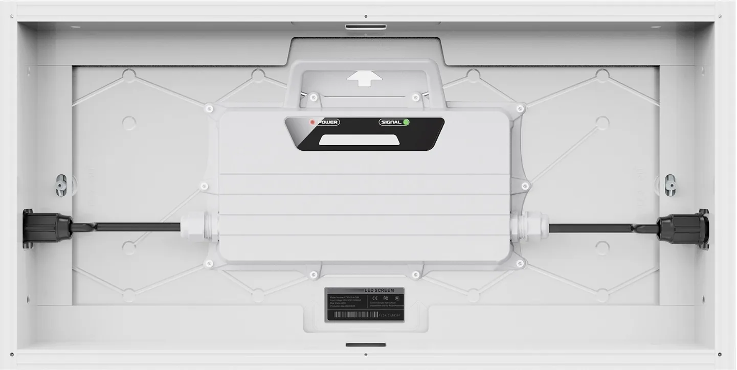
On the back of the panel, find the two locks — one left, one right. Twist each by hand to unlock. No tool needed.
Lift the panel out by its handle. Put it face up back in its box. Keep the empty frame.
3 — Build the frame
Step 3: Lay out the frames
Lay the empty frames in your grid: 5 across × 5 high.
Step 4: Bolt the frames together
Every place two frames touch gets 2 × M8 × 50 bolts and nuts — side to side and top to bottom. Your screen needs about 80 bolts.
Hand-tight first. Once the whole grid is in place, tighten them all with the large T-handle Allen key — snug, not overdone.
4 — Mount
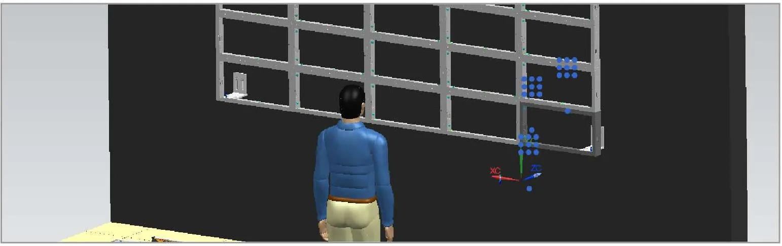
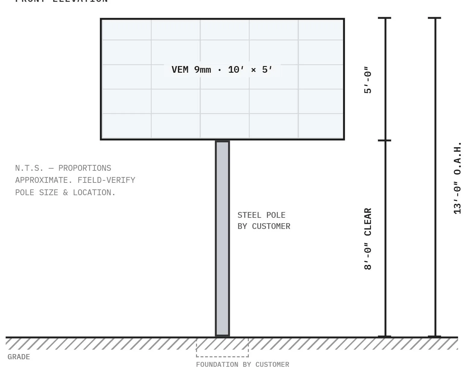
Step 5: Bolt the frame to the pole or structure
Bolt the frame grid to the structure with M8 × 50 bolts through the frame.
Your engineer designs the pole, foundation and attachment — see sheet 2 of your layout.
Wall mount instead?
5 — Panels in
Step 6: Put the panels in and lock them
Start with the bottom row and work up. Any panel fits any spot.
Set the panel into its frame — it drops into place when it's lined up right. Then lock it with the small T-handle Allen key, left and right.
6 — Wire it
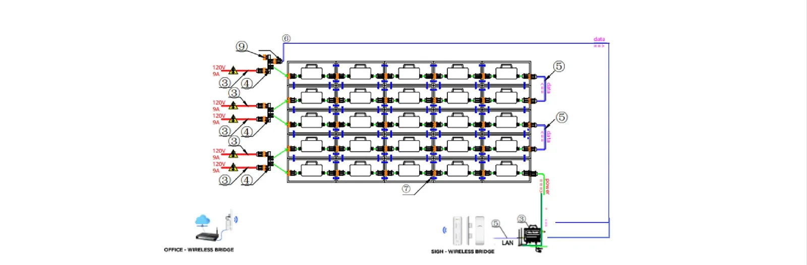
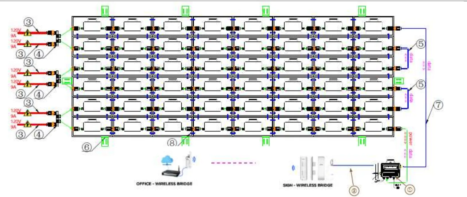
Work from the back. Sheet 3 of your layout shows the exact cable path for your screen.
Step 7: Link the panels in each row
Each panel has its own cable that carries power and data together.
Plug each panel into the next one along the row, from one end of the row to the other.
Step 8: Connect the row ends — power in, data zig-zags
- Left side — four-male adapters (3). Each one brings power in from the source and loops the data between two rows.
- Power cables (5). One per row, plugged into the adapters.
- Right side — double-female signal cables (2). They loop the data from one row to the next on the right.
The data snakes through every row and ends at the bottom right, next to the controller. Put the sealing cap on any open port. Sheet 3 of your layout shows the exact path.
Step 9: Mount and connect the controller
Fix the controller on the back of the screen, where both data cables reach without pulling.
- Primary data cable → runs up and over to the first row at the top.
- Backup data cable → the end of the bottom row, next to the controller.
Step 10: Power — licensed electrician only
The screen runs on 110–240 V. In the USA we set it up for 110 V.
Dedicated circuit(s), a lockable disconnect in sight of the sign, and GFCI / surge protection.
Your power needs · VEM 9 · 25 panels
- Max load
- 3,325 W (133 W × 25)
- Average load
- 1,000 W (40 W × 25)
- Max current
- 27.7 A @ 120 V
- Average current
- 8.3 A @ 120 V
- Power feeds
- 5 — one per row, ≈ 5.5 A each
- Circuits
- 2 × 20 A — or — 2 × 30 A
Circuits sized at 80% of breaker rating for a continuous load. Your electrician makes the final call per local code.
7 — Turn it on
Step 11: Final check
Step 12: Power on
Switch the disconnect ON.
Wait 1 to 3 minutes. The screen starts up and shows the demo message — usually the American flag.
8 — Connect to your network
Step 13: Set up the wireless bridge
The bridge comes as a pair:
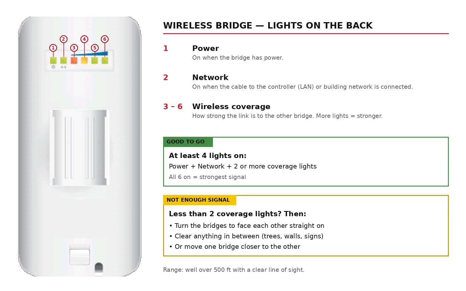
- The bridge marked LAN connects to the controller, at the sign.
- The other bridge goes at your building and plugs into your network.
Mount them so they face each other with nothing in between. With a clear line of sight they reach well over 500 ft.
Step 14: Install SunX and put up your content
Download and install the SunX software on your computer, then follow the video tutorials.
9 — Common questions
- Do panels have to go in a certain order?
- No. Every panel is the same. The controller tells each one what to show.
- How do I take out one panel later?
- From the front: put the small T-handle Allen key in the small holes, left and right, and unlock.
- How tight do the bolts go?
- Snug with the large T-handle Allen key in the box. No need to overdo it.
- Can I lift the whole screen at once?
- Small screens, yes — the frames are aluminum and light. Large screens: build row by row.
- Does the controller need a cover?
- No. It's waterproof and goes on the back of the screen.
- One panel is dark, the rest work. Why?
- Check its power and data connectors. Thanks to the backup data cable, one bad link doesn't darken the rest.
- 110 V or 220 V?
- Either — the screen takes 110–240 V. USA jobs are set up for 110 V.
- The bridge shows only 1 coverage light.
- Aim the two bridges straight at each other, clear the view, or move one closer. You need at least 2.
- How do I change what's on the screen?
- Use SunX — download it from the Download Center and watch the video tutorials.
Need help?
Our support team works through tickets — tell us your project and what you see.
Submit a support ticket